
***************************************************************************************************************************************************
NanoTest Vantage
Introducing the NanoTest Vantage
The new NanoTest Vantage system offers a complete range of nanomechanical and nanotribological tests in one flexible and user friendly instrument. With just one test platform a range of mechanical properties can be investigated, allowing a complete picture of material performance to be assembled.
- Nanoindentation (both quasi-static and dynamic)
- Nano-impact and fatigue
- Nano-scratch and wear
- Nano-fretting
- High temperature nanoindentation, nanoscratch and nanoimpact to 750ºC
- Low temperature nanoindentation and nanoscratch to -30ºC
- With sample and probe immersed in liquids
- In reduced oxygen/ purged conditions
- Under controlled humidity levels
Control environmental conditions to assess true ‘in-service’ properties
Material properties can vary greatly in response to the local environmental properties. The NanoTest Vantage is the only instrument which allows researchers to characterise and optimise their materials under the following range of conditions:
The NanoTest AdVantage
As well as offering unique capability, the NanoTest Vantage system has a range of advantages for the researcher:
The NanoTest is a fully modular system that allows the user to configure the system to meet their individual needs. The system can be expanded at a later date to include further modules, meaning that your system can evolve as your needs/ research interests change.
The NanoTest Vantage is designed to maximise output while minimising user time. Scheduling software allows the instrument to run 24/7.
Micro Materials are committed to strong customer service and research collaborations. Many of our testing modules have been developed in response to the needs of our customers.
Nanoindentation
Nanoindentation with the NanoTest Vantage
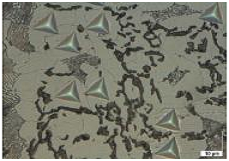
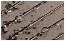
Figure 1 shows specifically targeted indents in gray cast iron
The NanoTest Vantage offers a combination of industry-leading instrumental stability with excellent performance over a wide load range.
Compliance to industry standards - The NanoTest Vantage is fully compliant to all relevant international nanoindentation standards including ISO14577 and ASTM E2546–07
How it works
The NanoTest Vantage uses electromagnetic force application and capacitive depth measurement to measure the elastic and plastic properties of materials on the nano-scale. For a full discussion of the theory of indentation, click here.
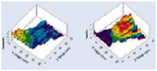 Figure 2 shows a 15 x 25 indent array (1μm pitch) mapping the distribution of hardness
Hardness and Modulus Mapping
And stiffness of intermetallic phases in a solder bond.
Rather than targeting specific unique sites, it is often useful to look at the distribution of hardness and modulus across a large area of interest. This can highlight areas of non-uniformity due to structural anomalies, variation in surface treatments or simply changes in properties at joints and boundaries. The stability of the NanoTest Vantage ensures excellent reproducibility of results over the duration of the test period.
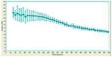
Figure 3 (above) shows the rapid profiling of hardness and elastic modulus as it varies with depth on a hard amorphous carbon film on a softer substrate
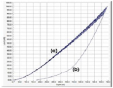 Figure 4 (left): The inflexion point (a) in the multi-cycle indentation marks the transition to substrate-dominated load support. A significant elbow is seen on the unloading curve (b) which relates to a phase transformation.
Depth profiling Load/partial-unload technique
Traditionally indentation was performed at one depth in the material. However, it is often of interest to investigate how hardness and modulus vary from the surface into depth in the sample. The ‘load/partial-unload’ technique included in the NanoTest software allows load cycling which allows hardness and modulus measurements to be made at different depths in the sample in just one indent cycle..
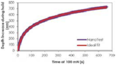
Figure 5 shows excellent agreement between fitted and experimental data for the creep of PMMA during a 700s hold at 100mN in the determination of the viscoelastic properties of polymers.
Indentation Creep
In addition to providing reliable measurements of hardness and modulus, excellent system stability enables tests of longer duration, such as indentation creep experiments. These can be used to reliably extract properties such as the stress exponent or creep compliance and, in conjunction with the high temperature module, the activation energy for creep processes.
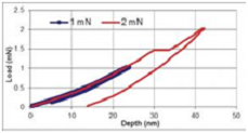 Figure 6: 1mN peak load indentations in sapphire show contact to be completely elastic. Raising the peak load to 2mN shows elasto-plastic contact
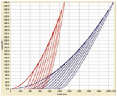 Figure 7 shows 10 indentations to peak loads of 100-500 mN on fused silica (blue) and sapphire (red).
Wide load & depth range
The NanoTest Vantage offers excellent load & depth ranges, with a dynamic resolution system which optimises the load and depth resolutions according to the peak load/depth set. This ensures excellent resolution throughout the ranges. The low noise floor and high sensitivity enables accurate measurements of thin films for MEMS applications.
Theory of Nanoindentation
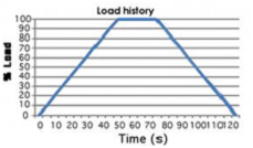
Depth Sensing nanoindentation systems allow the application of a specified force or displacement history, such that force, P, and the displacement, h, are controlled and/or measured simultaneously and continuously over a complete loading cycle
1) Setting experiment parameters
The user defines a load cycle, consisting of load, hold and unload periods.
Loading and unloading rates can be programmed, and experiments can be controlled either by setting a peak load or a peak depth.
The shape of this loading curve is extremely important and will vary depending on the sample being tested. For example, polymers and soft materials will need a significantly longer creep period in order to ensure the creep exponent has been removed during unloading. Peak loads (and hence depths) chosen will also affect results, due to ‘indentation size effects’.
2) How are hardness and modulus calculated?
The instrument starts with the probe in contact with the sample surface, using a tiny contact load.
The load is then increased at a given rate, as determined by the user. As the load increases, the depth of the probe in the material will increase.
Once the probe has reached the pre-set experiment target (this can be either a maximum load or a maximum depth), it is good practice to then hold at peak load in order to look at creep properties. The probe is then removed from the sample, leaving a residual indent.
Hardness and modulus are calculated using data taken from the slope of the tangent to the unloading curve.
The extremely small force and displacement resolutions possible with the MML NanoTest, which are as low as 3nN and 0.001nm, respectively, are combined with very large ranges of applied forces (0 - 500mN) and displacements (0-50µm or more). This allows the NanoTest to be used to characterize nearly all types of material systems.
The following properties may be measured:
- Hardness
- Modulus
- Creep
- Plastic Depth/Contact Depth
- Elastic recovery parameter
- Plasticity Indices
Benefits over traditional hardness testing
During traditional macro or micro scale indentation, a hard tip, typically a diamond, is pressed into a sample with a known load. After a set period of time the load is removed. The area of the residual indentation in the sample is measured and the hardness, H, is defined as:
H = P/Ar |
where P = Maximum Load |
|
Ar = Residual Indentation Area |
In order to determine the indent area, a powerful microscope is needed, and valuable time-dependent information will be lost in the . However, an alternative method may be used - depth sensing indentation.
Nano-impact
Nano-Impact & Fatigue
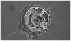
Figure 1: Nanoimpact damage
Repetitive contact through impact allows investigation of fatigue and fracture processes. As an “in situ” wear test it is possible to detect the onset of damage and obtain mechanistic information that can be much more beneficial in intelligent coatings design than merely reporting an average wear rate or hardness.
Nano-Impact was developed and has been patented by Micro Materials (EU Patent 1095254) and is fast becoming a vital research tool in the very best worldwide research institutions. Operating at high strain rates, nano-impact provides valuable additional information to nanoindentation.
How it works
Probe acceleration impact for low cycle fatigue:
- Using solenoid activation the impact probe is accelerated rapidly over a precisely chosen distance (e.g. 10 µm above the sample) to impact the surface at very high strain rate. Single and repetitive impacts are possible.
- Popular testing approach for investigating low cycling fatigue, work hardening, yield stress and dynamic hardness.
- Applied load, impact angle, acceleration distance, indenter geometry are user-definable.
The enhanced damping of PTFE is clear.
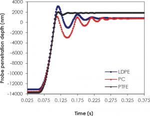
Figure 2 shows single impacts on a range of polymeric materials. The enhanced damping of PTFE is clear.
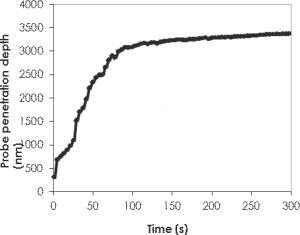
Figure 3 shows repetitive nano-impact tests on a 7-8% Yttria Stabilised Zirconia (thermal barrier coating) that was previously aged for 24 hr at 1500ºC.
Sample Oscillation impact for high cycle fatigue:
- Piezoelectric oscillation system, signal generator, amplifier and software for control and data analysis.
- High cycle fatigue tests with oscillation frequencies up to 500 Hz and amplitudes up to 5 µm
- Enables both impact and contact fatigue tests to be performed depending on the magnitude of the static load.
The rapid nano-impact test shows the decreased resistance to multiple impacts after thermal ageing of the TBC consistent with results from erosion tests.
Each point shown represents one impact.
Nanoscratch
Figure 1: Ramped scratches to 500mN show brittle fracture of 1.5 μm TiFeN films on Si at high load.
Thin films and coatings (from a few nm to about 1μm thick) need to be optimised both in the mechanical properties and tribological performance. Typically, this is done with a combination of indentation and scratch tests. Conventional scratch test conditions are not appropriate for these types of materials as they were developed for testing thicker coatings. Instead the nano-scratch & wear module can provide what is needed.
How it works
The sample to be tested is moved perpendicular to the scratch probe whilst the contact is either held constant or ramped at a user-defined rate. Throughout the test the probe penetration depth and tangential (frictional) load are continuously monitored. Single and multi-pass tests are possible.
The Nano-Scratch & Wear module has found many applications in sectors as diverse as optical, microelectronics, polymer/biomaterial, and tribological coatings.
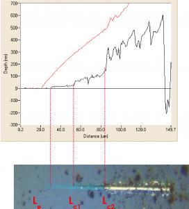
Ramped scratch, corrected for baseline sample topography A pre-scratch scan was carried out using an ultra low contact force in order to assess baseline sample topography.
The red line shows the on-load probe depth, which represents elastic and plastic depth. After 20μm the load is ramped at 2.5mN/s.
The black line shows the residual (plastic) depth once the scratch load has been removed. This has been corrected for initial sample topography.
Friction measurements are carried out throughout.
Nano-fretting
Nano-fretting is an accelerated reciprocating wear test, which allows oscillation of sample whilst applying a known load. It differs from conventional wear testing (carried out using the nano-scratch and wear module) as follows:
- It uses a large radius spherical probe, giving low contact pressures
- It is a high cycle test, with up to 1 million cycles in one experiment
- It uses very small amplitude oscillations, allowing reproduction of true-fretting (partial slip) to nano-wear (full slip).
The user can vary both the frequency and amplitude of sample oscillation.
The extremely low thermal drift experienced by the NanoTest allows long duration wear tests such as these to be carried out with no need for drift corrections.
High & Low Temperature Control
Temperature Control
Material properties can vary greatly with changes in temperature. Thus, when developing or characterising materials or coatings which are to be used in high temperature applications, test conditions should mimic in-service conditions as closely as possible.
The NanoTest Vantage hot stage allows (1) Nanoindentation (2) Nano-Scratch & Wear (3) Nano-Impact & Fatigue to be performed at temperatures of 750 ⁰C.
The NanoTest Vantage cold stage allows (1) Nanoindentation (2) Nano-scratch & Wear to be carried out at temperatures down to -30ºC.
High Temperature Stage
How it works
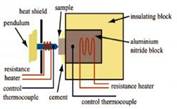
The horizontal loading design of the NanoTest Vantage is critical for accurate and reliable testing at elevated temperatures. The configuration is shown in Figure 1.
Figure 1
Important features
- Horizontal Loading – No heat flow into the loading head or depth measurement sensors, which are positioned to the left of the probe.
- Isothermal contact – The NanoTest Vantage hot stage controller uses separate heating of both probe and sample to ensure no heat flow occurs during the indentation process (UK patent).
- Highly localised heating – ensures instrument stability
- Time-dependant measurements - As no significant thermal drift occurs during elevated temperature measurements it becomes possible to perform longer duration tests such as indentation creep tests.
- Non-ambient gases - The NanoTest Vantage has a choice of a temperature controlled environmental chamber or a purging chamber that provides a choice of ambient atmospheres and vastly reduces oxidation of samples.
Wear prediction of PVD coatings for high speed turning
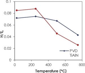
Figure 2 shows high temperature indentation on PVD coatings and the Hardness/Modulus ratio, which strongly influences wear in a variety of tribological situations. Nanoindentation on the PVD coatings shows why TiAlN outperforms TiCN in high speed turning despite having a lower hardness value at room temperature.
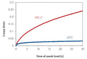
Figure 3 shows that the creep strain on Ti6Al4V is notably higher at 650ºC than 25⁰C and that in high speed cutting operations, wear resistance and lifetime of coated cutting tools are strongly correlated with their high temperature mechanical properties..
Cold Stage
How it works
The NanoTest cold stage uses three stage Peltier cooling stages on both the indenter and the sample, ensuring isothermal contact during testing. An environmental enclosure is used to control the ambient conditions around the test area.
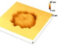
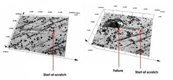
Nano-scratch testing of DLC coating to –30°C
Coating properties were seen to vary greatly with temperature. The figure on the left shows a scratch track made at room temperature, exhibiting some plastic damage but no critical failure.
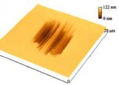
The figure on the right shows the same scratch carried out at -30º, showing failure along the scratch track. Scratches run from right to left on each image.
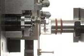
Liquid Cell
Mechanical properties of materials often vary considerably when in their normal fluid environment compared to the usual laboratory dry testing conditions. Probing the mechanical properties of biological samples in fluid media should prove a closer mimic of in vivo conditions than conventional dry nanoindentation testing.
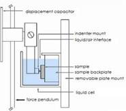
How it works
The testing capability of the NanoTest has been extended by the development of a liquid cell allowing Nanoindentation, Nano-scratch & Wear testing of samples fully immersed in liquid. A friction transducer extension also allows immersed sample friction measurements. The fluid cell works with the existing pendulum design and the horizontal loading has several key advantages for testing in fluid.
- Constant buoyancy force
- Constant surface tension on loading column
- Liquid is not underneath capacitor
Liquid cell applications and investigating of soft materials immersed in liquids includes:
- Tribology
- Corrosion
- Tissue mechanics as a function of source, disease state, and exposure to soluble toxins or drugs
- Tissue properties as a function of submicron position within the tissue
- Porous materials (bone, cement, chemomechanics)
- Biocompatibility and biomaterials
- Dental enamel
- Micro particle friction and wear
- Polishing mechanics
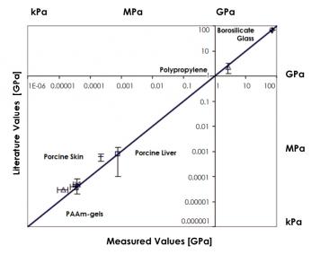
Figure 3 shows the measured Elastic modulii of various specimens (Borosilicate glass, Polypropylene, Porcine liver, Porcine skin, PAAm-gels in various mol concentrations) are in very good agreement with literature values. The data ranges eight orders of magnitude.
Investigate a wide range of hardness values
Research by MIT has shown that nanoindentation with the NanoTest liquid cell could be performed with sample fully immersed in liquid for materials spanning several orders of magnitude of stiffness from highly compliant gels to biological tissues.